This page is about my analog spring reverb project. My goal was to build an analog circuit that would work with any commercial spring tank.
The goal was to make an analog spring reverb using real spring tanks.
The idea is similar to the Anasounds Element but is not a clone of it.
I built it by recycling an old Yamaha CDX-590 CD player.
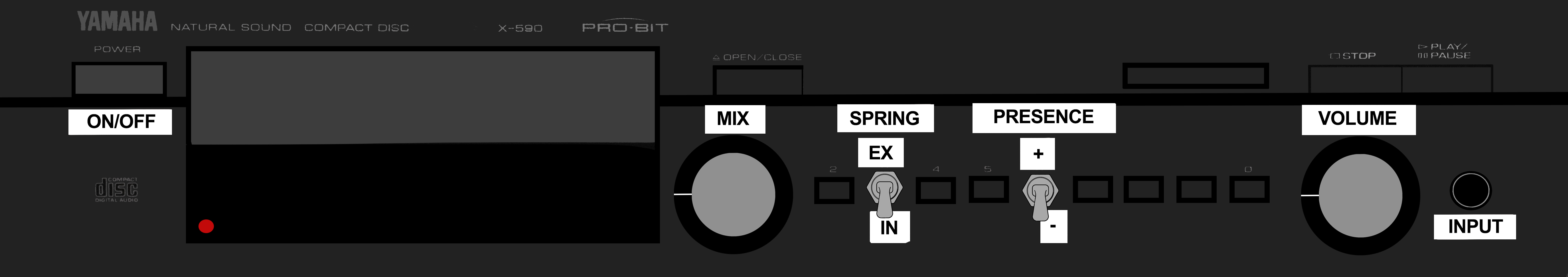
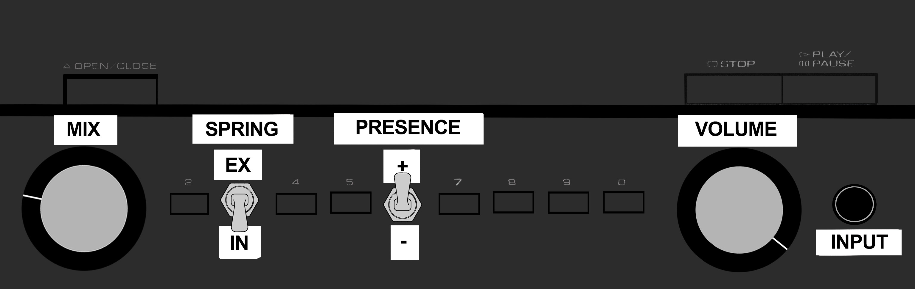
Here are the controls:
- MIX knob, controls the amount of reverb mixed with the dry signal. At 0, it's a full dry sound at maximum it's full wet.
- SPRING toggle switch, lets you choose between internal (IN) and external (EX) spring tank.
- PRESENCE toggle switch, changes the value of one specific condenser in the schematic (see below).
- VOLUME knob, self-explanatory.
Dry

Stratocaster, Lace sensor gold neck pickup, Blackstar HT5 clean channel
Gibson SG, Seymour Duncan SH4 bridge pickup, Drop C# tuning, ProCo Rat before reverb into Blackstar HT5 clean channel
Internal Spring (Accutronics 8BB2C1B)
Mix 25%, Presence on low setting

Stratocaster, Lace sensor gold neck pickup, Blackstar HT5 clean channel
Gibson SG, Seymour Duncan SH4 bridge pickup, Drop C# tuning, ProCo Rat before reverb into Blackstar HT5 clean channel
Mix 50%, Presence on low setting

Stratocaster, Lace sensor gold neck pickup, Blackstar HT5 clean channel
Gibson SG, Seymour Duncan SH4 bridge pickup, Drop C# tuning, ProCo Rat before reverb into Blackstar HT5 clean channel
Mix 75%, Presence on low setting

Stratocaster, Lace sensor gold neck pickup, Blackstar HT5 clean channel
Gibson SG, Seymour Duncan SH4 bridge pickup, Drop C# tuning, ProCo Rat before reverb into Blackstar HT5 clean channel
Mix 100%, Presence on low setting

Stratocaster, Lace sensor gold neck pickup, Blackstar HT5 clean channel
Gibson SG, Seymour Duncan SH4 bridge pickup, Drop C# tuning, ProCo Rat before reverb into Blackstar HT5 clean channel
Mix 25%, Presence on high setting
Stratocaster, Lace sensor gold neck pickup, Blackstar HT5 clean channel
Gibson SG, Seymour Duncan SH4 bridge pickup, Drop C# tuning, ProCo Rat before reverb into Blackstar HT5 clean channel
Mix 50%, Presence on high setting

Stratocaster, Lace sensor gold neck pickup, Blackstar HT5 clean channel
Gibson SG, Seymour Duncan SH4 bridge pickup, Drop C# tuning, ProCo Rat before reverb into Blackstar HT5 clean channel
Mix 75%, Presence on high setting

Stratocaster, Lace sensor gold neck pickup, Blackstar HT5 clean channel
Gibson SG, Seymour Duncan SH4 bridge pickup, Drop C# tuning, ProCo Rat before reverb into Blackstar HT5 clean channel
Mix 100%, Presence on high setting

Stratocaster, Lace sensor gold neck pickup, Blackstar HT5 clean channel
Gibson SG, Seymour Duncan SH4 bridge pickup, Drop C# tuning, ProCo Rat before reverb into Blackstar HT5 clean channel

Part 0 - Power supply stage
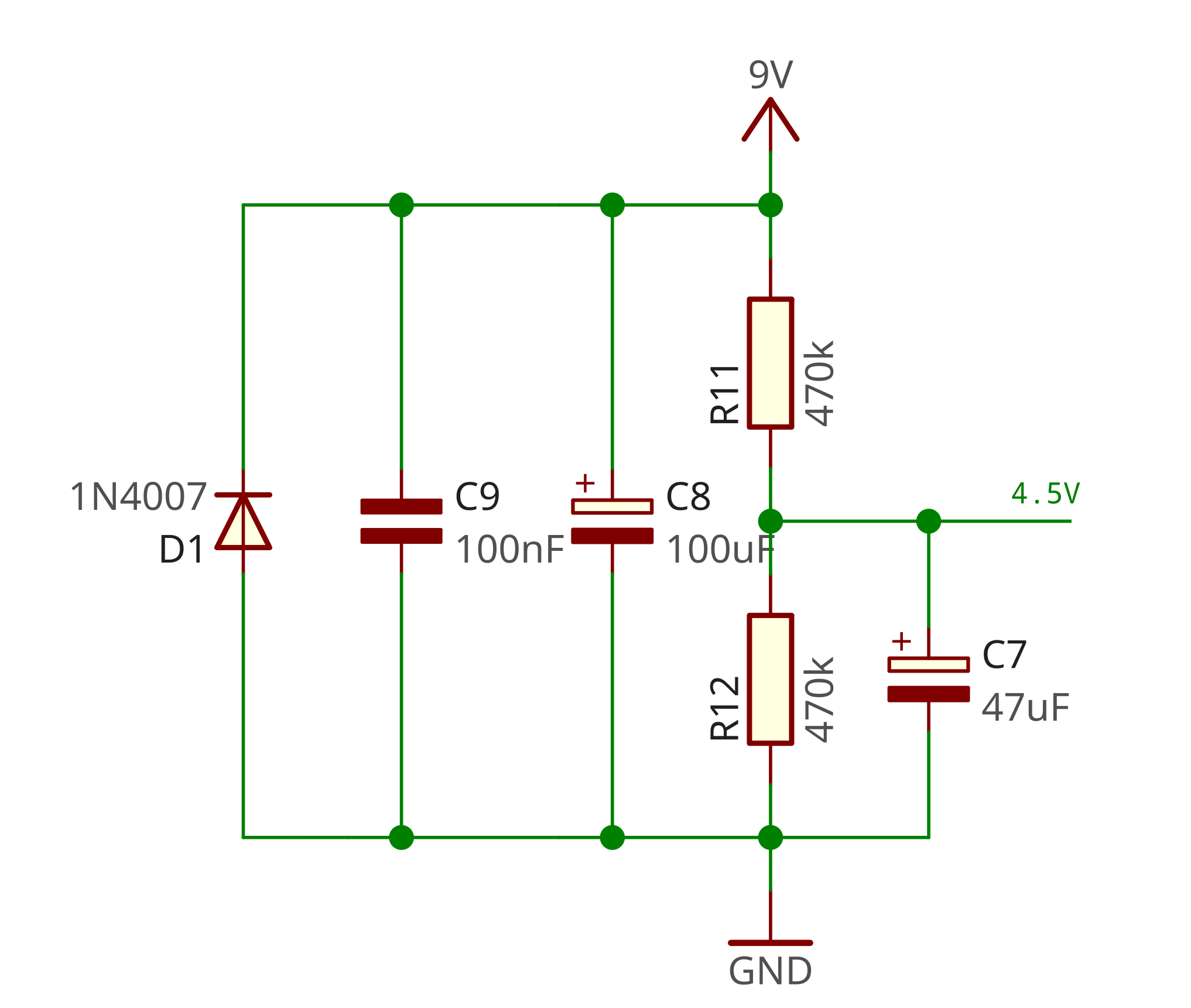
Before diving into the parts that actually change our guitar signal, we need to create a 4.5V point in our circuit.
We're using 2 TL072 OpAmps. Those OpAmps are powered by a 9V current and connected to ground.
The 4.5V point we're creating allows us to center the signal to avoid unwanted distortion when going through OpAmps.
This is a basic voltage divider circuit. (Wikipedia link)
The important thing is to use 2 resistors with the same value to have a stable 4.5V.
The diode and capacitors are here for protection purposes.
This is exactly the same as a Tube Screamer power supply stage you can find in this example.
Part 1 - Input buffered splitter
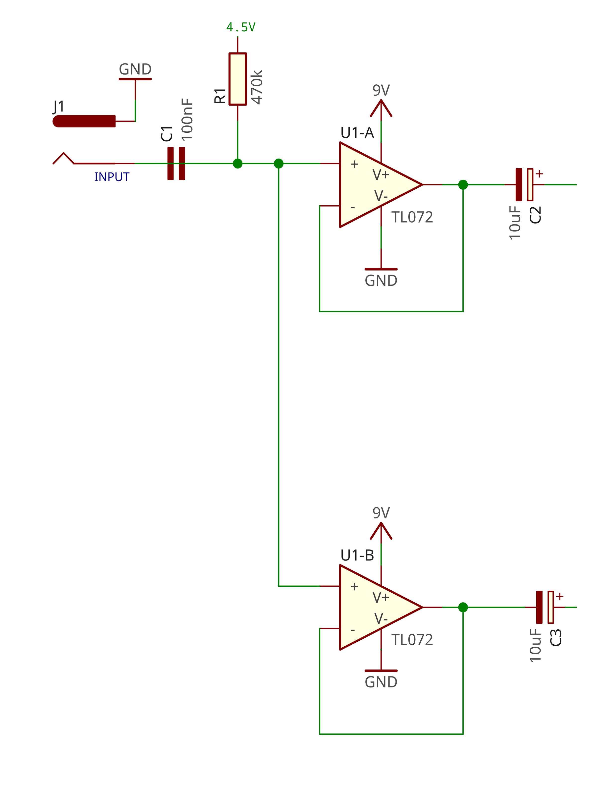
First, we need to do two things :
- - Split our signal in two. Then the first signal will go through the spring tank whilst the other signal remains unaffected.
- - Adapt the impedance to match the input of the spring tanks.
To do that, I got inspired by Musikding's "The Splitter" schematic, which does exactly what I need. (link)
Part 2 - Reverb tank selector
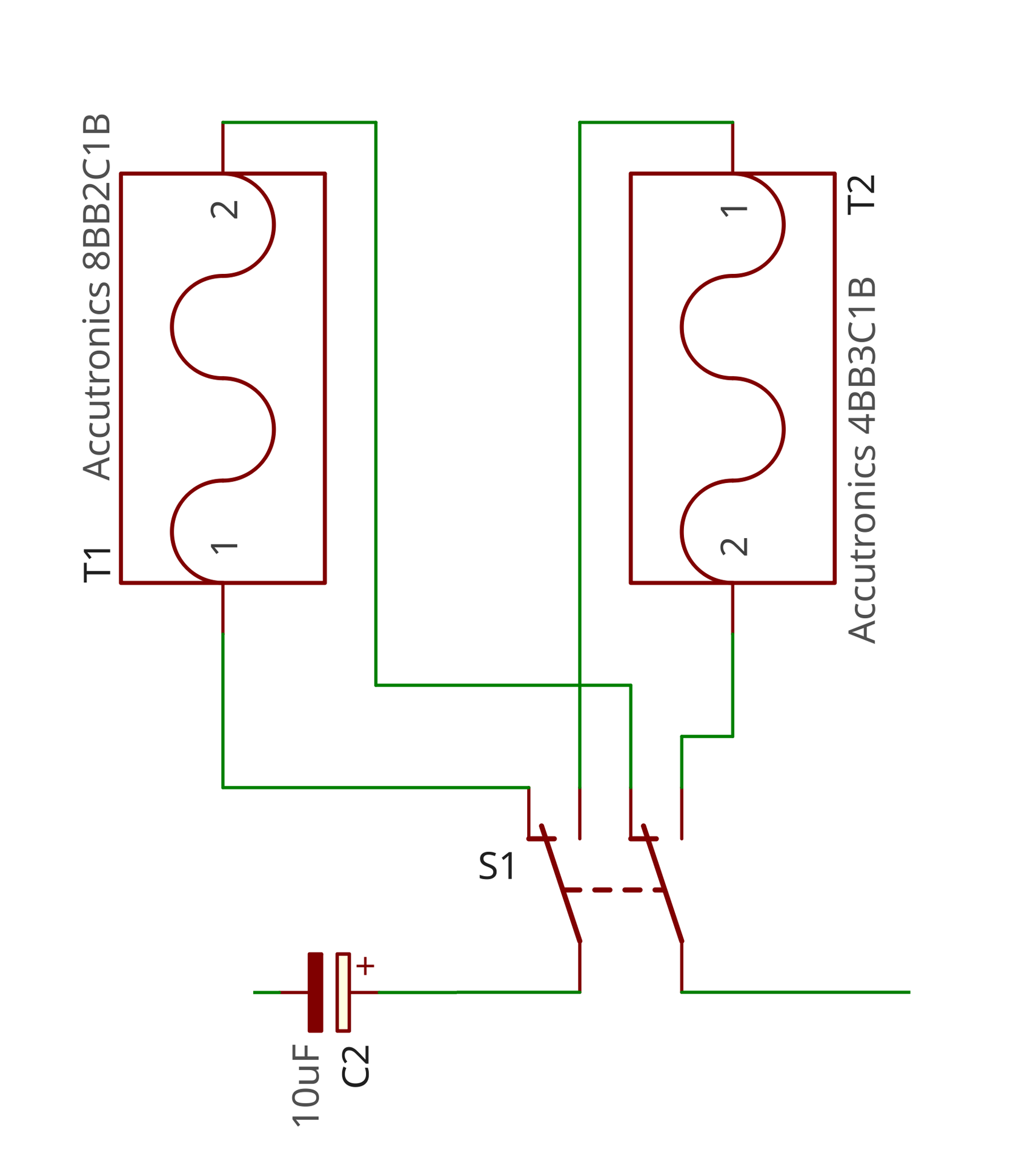
This is simply a 2SPDT toggle switch so you can switch between two reverb tanks.
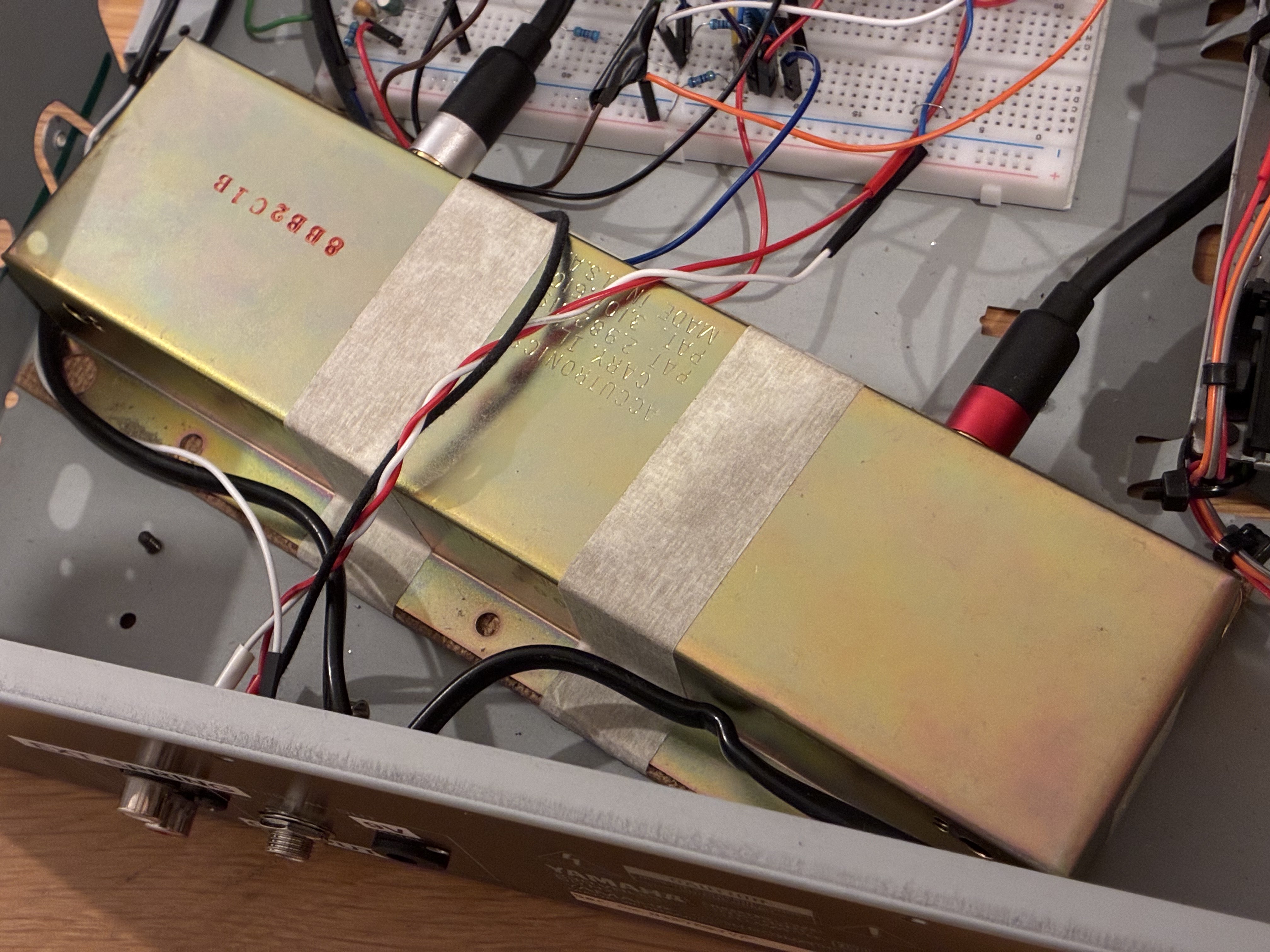
I'm using an Accutronics 8BB2C1B reverb tank inside my reverb unit and a bigger Accutronics 4BB3C1B external reverb tank.
My goal with this project was to design a circuit that doesn't use tubes and works with any reverb tank.
You can adapt this part to your needs depending on how many reverb tanks you have.
Part 3 - Post tanks boost
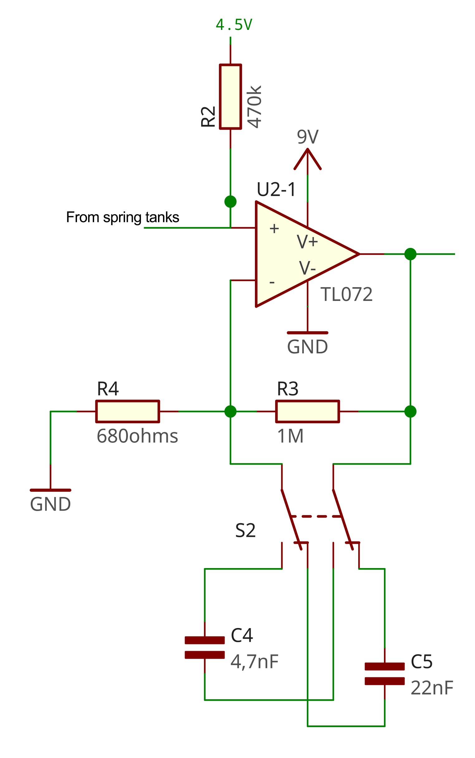
This part is right after the reverb tanks.
By going through the reverb tank, we lost a lot of volume.
What we need at that point is to boost the signal to get that volume back but trying not to introduce too much noise in our signal.
An operational amplifier allows us to have enough signal boost with low noise, unlike transistors.
At first, I was going for transistors, like on a Electro-Harmonix LPB-1, but there was just too much noise.
I use a simple non-inverting amplifier (Wikipedia link)
The formula for the output tension here is $$Vout = Vin({R3 \over R4}+1)$$
With R3=1M ohms and R4=680 ohms, output tension is about 1470 times (!!!) the input tension.
That's how small the post reverb tank signal was.
C4 and C5 - Presence capacitors
The 2 capacitors C4 and C5 are here for filtering purposes. I chose two values by ear after many tests.
You can experiment with other values. I think under 1nF/2.2nF it's not filtered enough and above 68nF/100nF it's too filtered.
Again, it depends on what you like and the spring tanks you have.
Part 4 - Mix knob
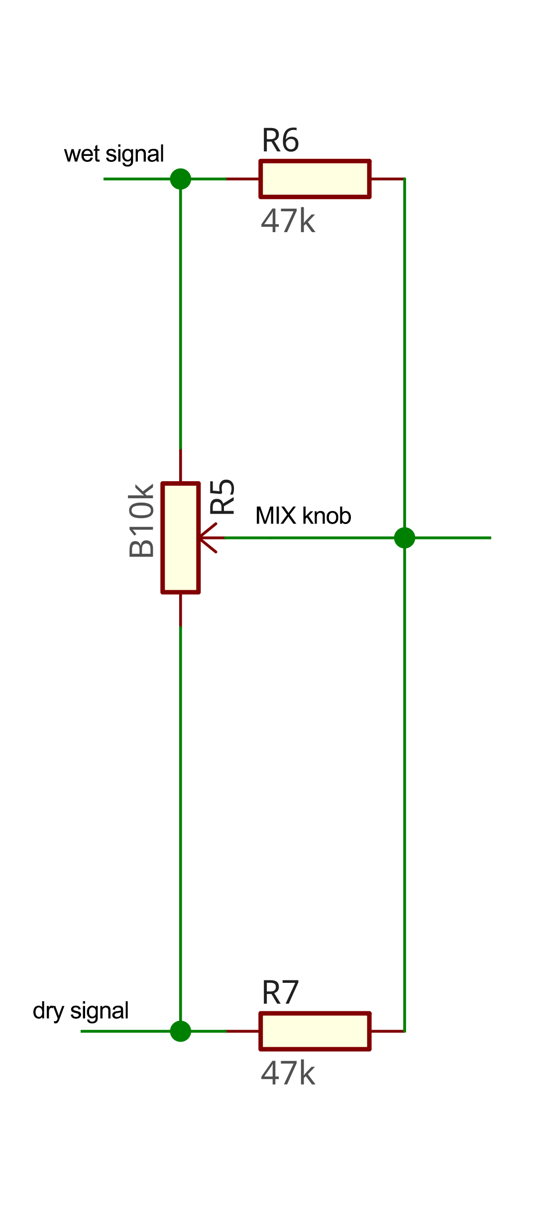
Here is where our dry and wet signals meet.
Part 5 - Volume output
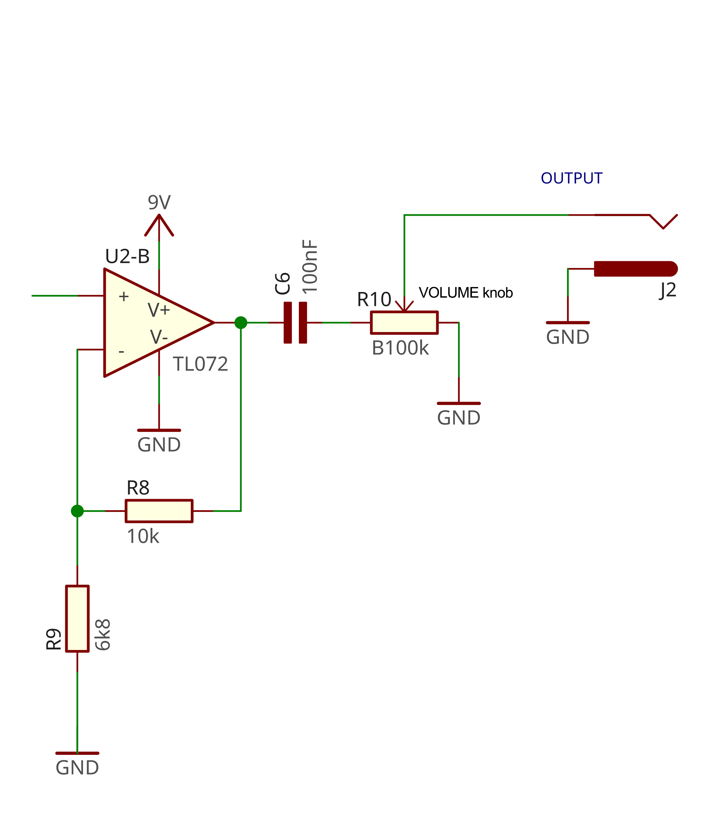
This is another non-inverting amplifier, with not a lot of gain so it does not add saturation to our signal.
The formula for the output tension here is $$Vout = Vin({R8 \over R9}+1)$$
With R8=10k ohms and R9=6k8 ohm, output tension is 2.47 times the input tension
The point of the first non-inverting amplifier was to match the wet signal with the dry just before the mix knob.
Here, it's used to have a bit more output volume.
I hope you liked this presentation.
Feel free to visit my GitHub account to see my other projects :)
Here are a few photos of my prototype. Enjoy :)

External spring, Accutronics 4BB3C1B.
External spring, Accutronics 4BB3C1B.
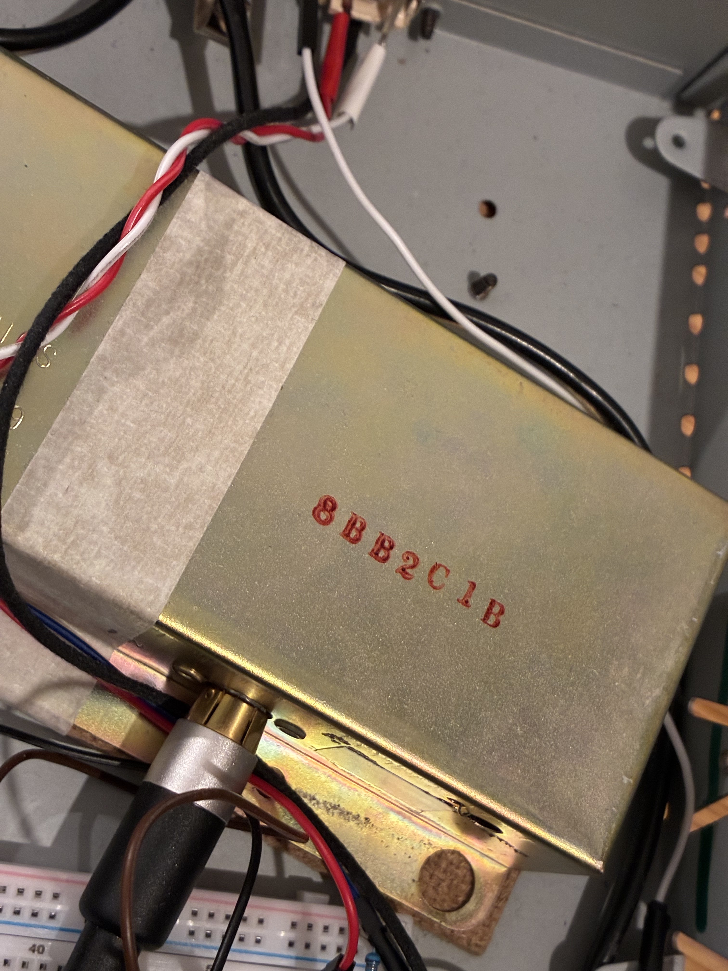
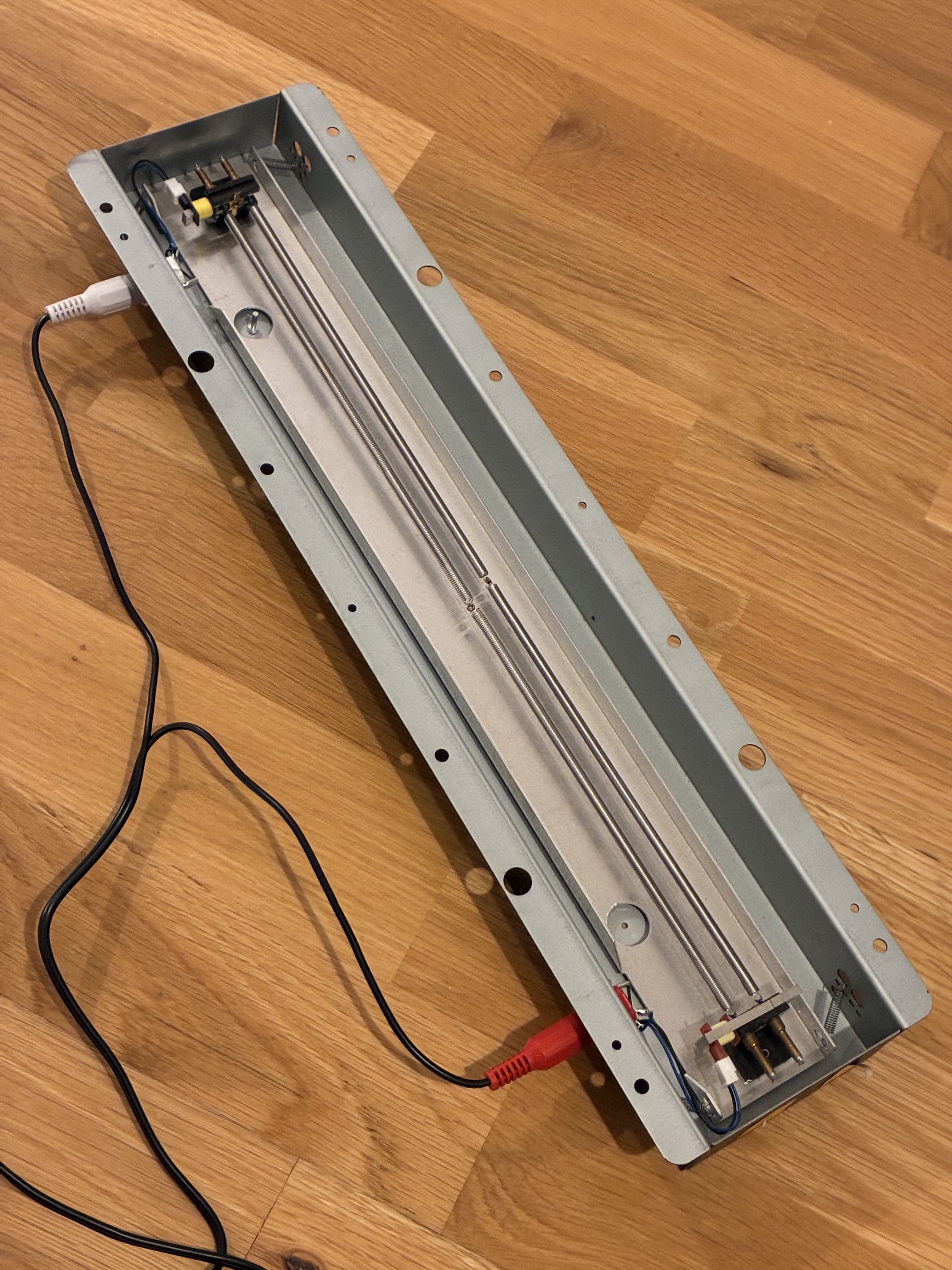
Internal spring, Accutronics 8BB2C1B.
Internal spring, Accutronics 8BB2C1B.
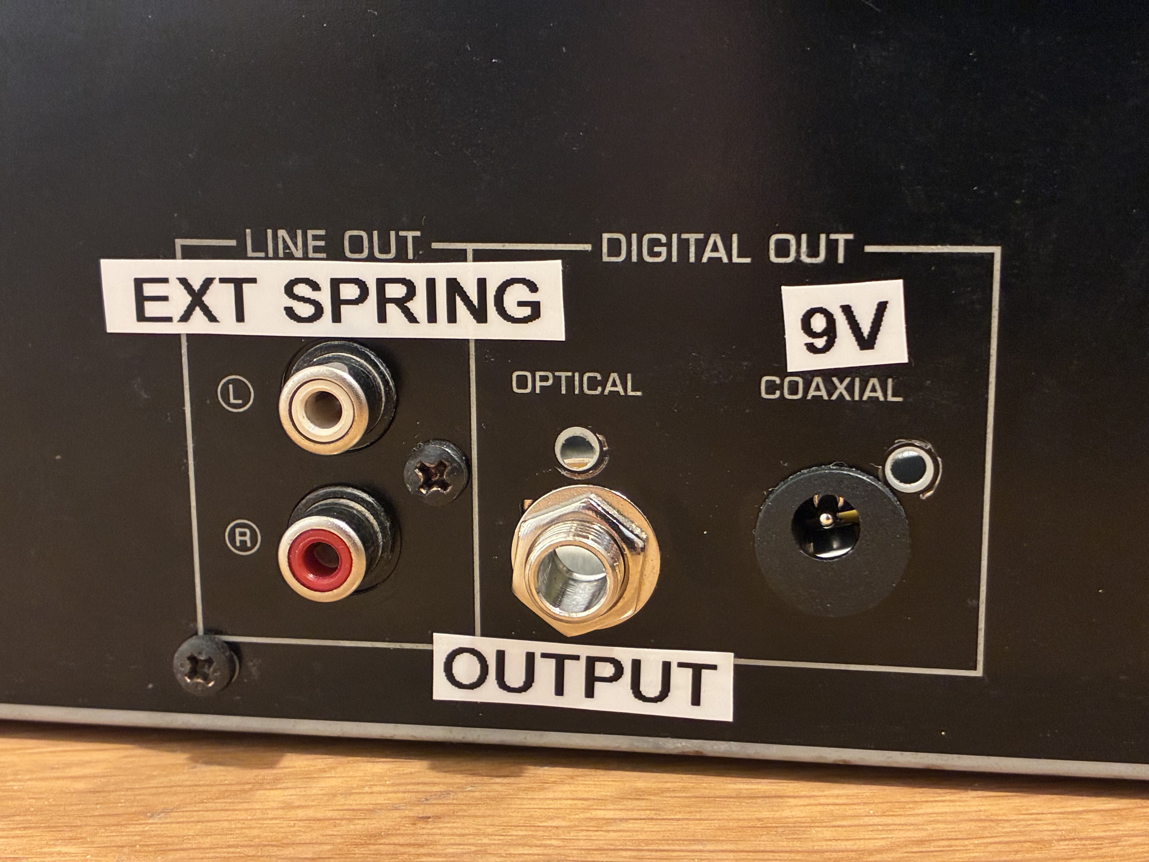
Back of the spring reverb (external spring connector, output and 9V).