We already have plenty of Big Muff Pies, so I made a simple fuzz tart.
There is no bad fuzz pedal.
The goal of the first fuzz pedal was to recreate a broken sound. Then, it evolved throughout the years but it remained a heavily harsh distorted sound.
There is no bad fuzz pedal because every fuzz pedal could be used by someone in the right context.
Also, if you look at some of the first fuzz circuits, you'll see how simple they are.
For example, a Fuzz Face only has around 10 components.
The beauty of fuzz pedals is that minor changes in those simple circuits can have massive consequences in the sound.
For this project, I was looking for simple basic circuits I could easily make on a breadboard.
I found out about the Bazz Fuss circuit (More info) and tried a few things based on this circuit.
First, I changed the diode for a LED. Then I added a clean boost stage before the circuit, like the Big Muff Pi.
The Tatin Fuzz name is obviously a reference to the Big Muff Pi and because I also use a transistor-based clean boost going into a transistor-based clipping circuit, but this is not a Big Muff Pi clone.
In a world full of Pies, I made a French tart.
Work in progress...
Made using LibrePCB
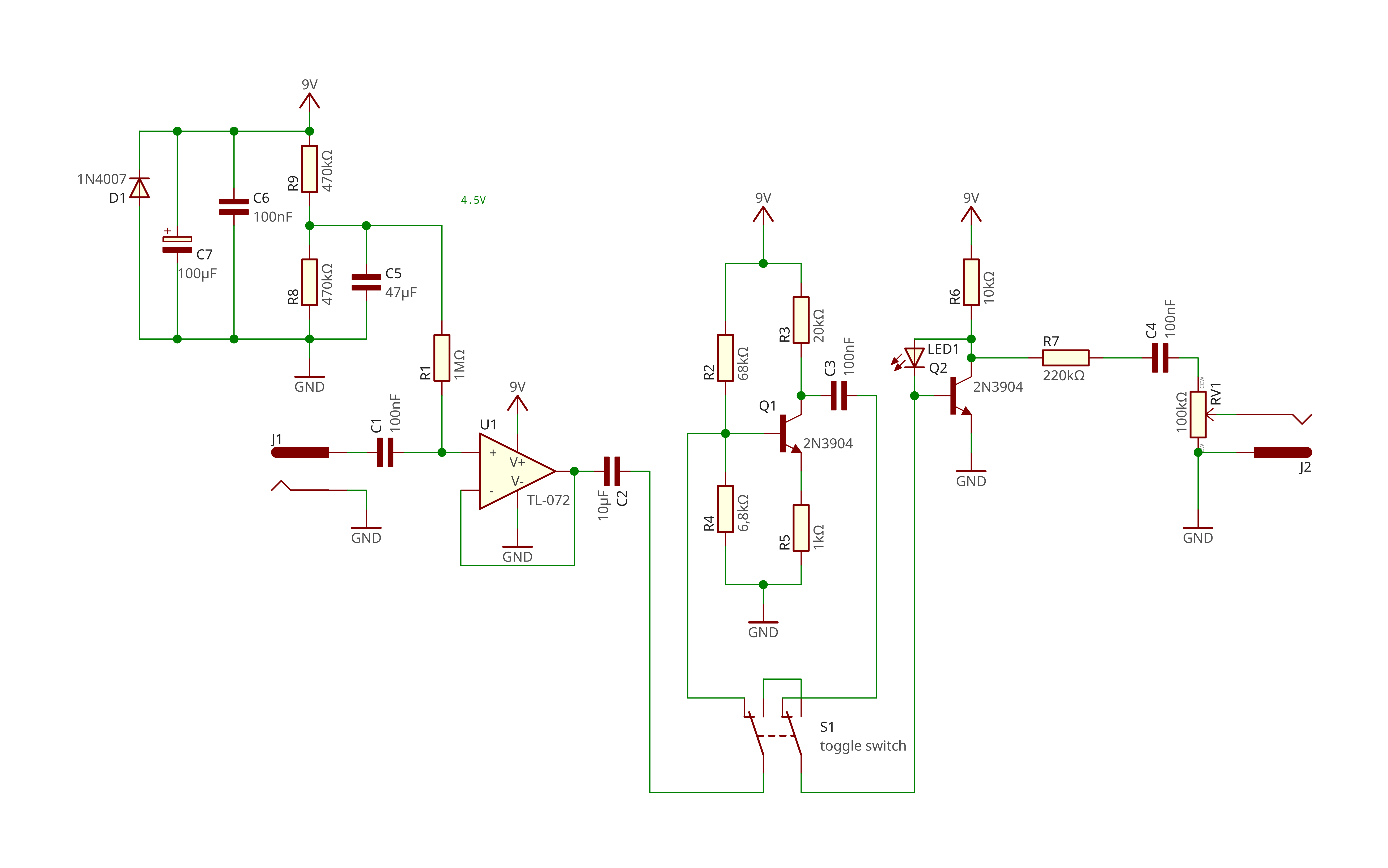
Here is the full schematic of the tatin fuzz pedal. Let's see how each part works.
Part 0 - Power supply stage
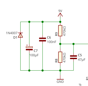
Before diving into the parts that actually change our guitar signal, we need to create a 4.5V point in our circuit.
We're using a TL072 OpAmp. This OpAmps is powered by a 9V current and connected to ground.
The 4.5V point we're creating allows us to center the signal to avoid unwanted distortion when going through OpAmp.
This is a basic voltage divider circuit. (Wikipedia link)
The important thing is to use 2 resistors with the same value to have a stable 4.5V.
The diode and capacitors are here for protection purposes.
This is exactly the same as a Tube Screamer power supply stage you can find in this example.
Part 1 - Input buffer
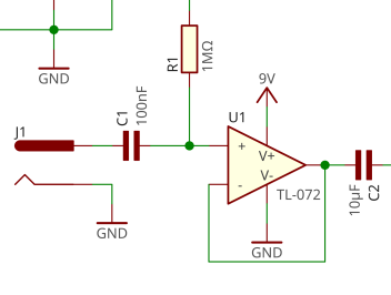
First, when entering the circuit, we're using a simple buffer for impedance matching.
Part 2 - Switchable boost
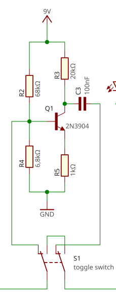
Before going through the fuzz circuit, we're using a simple signal booster.
We're using a 2N3904 transistor in Common Emitter configuration, just like the Electro-Harmonix LPB-1.
Actually, if you just take this part of the circuit, with a 100nF capacitor first and a pot in series after the C3 capcitor, you got yourself a simple transistor-based clean boost!
Here, R2 and R4 are used to biased the transistor. The 1:10 ratio is important but can be adapted to your specific transistor.
The formula for the output gain here is $${R3 \over R5}$$, which is 20 in this case.
Changing the values will give you more or less boost and can even give you a slight crunchy sound.
I use a toggle switch to activate or not the boosting signal, so instead of a boosted fuzz with a drive or fuzz knob, I have a fixed fuzz that is boosted or not.
Part 3 - Fuzz output
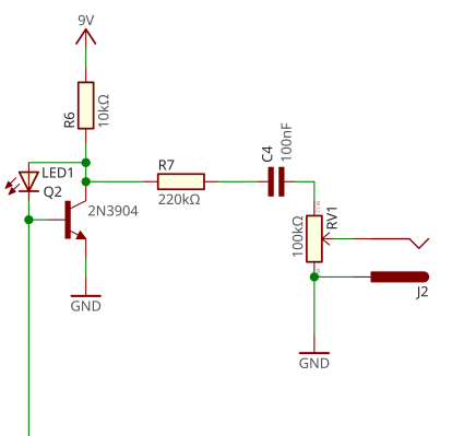
This last part is what makes this a fuzz pedal.
When I got back into electronics and guitar pedals, I was looking for simple basic circuits I could easily make on a breadboard.
This is how I found out about the Bazz Fuss circuit (More info).
It's a very simple circuit with just one transistor, a diode, a couple resistors and capacitors.
That's what I like about fuzz pedals: they're simple and every minor change to the circuit can have a huge impact.
I used another 2N3904 transistor and the main difference is the use of a LED instead of a simple diode.
I also added a 220 kOhms resistor at the output to reduce the maximum volume of the pedal.
Work in progress...